Are you having an issue with your EV² gauge or gauges? Check out our simple to follow troubleshooting guide below. This guide will help identify exactly what is causing the issue you're experiencing with your gauge and guide you how to fix it. If you need more assistance after using the guide we encourage you to reach out to our tech department for further assistance. You can reach Don at 800-888-8065 ext. 3402.
All gauges:
1. Check if the gauge pointer homes (moves counterclockwise towards pointer stop) on power-up. You should hear a faint noise from the gauge motor for a moment, and see the pointer move against the pointer stop,then it should move away from the pointer stop to the value the sensor currently indicates. If the gauge is newer than S/N C91 then it will have a red warning LED at the bottom (6:00 position) of the dial, this LED should illuminate briefly while the pointer is homing. If it is a pressure gauge and does not detect a sensor within normal operating range then the pointer will stay on the pointer stop (below 0) after homing. On all gauge types, if the gauge detects an out of range signal after previously detecting an in range signal during this key cycle (typically due to an intermittent connection to the sensor), the pointer will move to the straight down (6:00) position. For any results indicating a connection problem at the orange connector, use a pair of pliers and the black plastic wire insertion tool (R72023, making sure the solid end is towards pin #6) to FIRMLY press the wires into the orange connector.
2. If the gauge homing function does not work &/or the LED does not illuminate briefly when power is applied, check your ignition input voltage at the pins into the gauge. You should have battery voltage into pin #1, ground at pin #3. Check voltages at the exposed metal portion of the terminal on the orange connector (accessible from the top of the gauge with the connector plugged into the gauge). If you do not see the voltage across those terminals; check for voltage between the actual wires (you can probe the cut ends of the wires). If you do not have voltage across the wires, check your source (vehicle) connection for the wires. If you find voltage at the wires but not at the terminals, check that the wires are sufficiently seated into the orange connector to make electrical contact. If you have other EV2 gauges (even if different types such as a pressure gauge connector to test a pyrometer) you can plug the gauge head into the connector for another working gauge to quickly see if it homes and illuminates the warning LED with a known good connector. If you definitely have power between these two terminals (not just to the wires but to the terminals within the orange connector) but still no homing, then the gauge should be replaced.
3. If your backlighting is not working but the gauge is otherwise functioning, check voltage between the gauge pins 2 & 3 (checking at the exposed metal portion of the terminal on the orange connector). With the dimmer turned up all the way, you should see something close to battery voltage. If you have a 3rd generation (2003 or newer) Dodge, and the gauges dim significantly (more so than the factory dash) when your grid heater cycles, you may have the older software version in your gauges. Check the gauge label for a version number (letter “A” followed by a 3-digit number). The updated lighting is on versions A134 & higher. Some older gauges did not have any version number on the label. If you need the updated lighting software for a gauge older than A134, contact ISSPRO Customer Service to send back for reprogramming.
Standard Pressure Gauges (Boost Pressure, Oil Pressure, Exhaust Backpressure, Trans Pressure, Drive Oil Pressure):
4. If the gauge performs the homing functions of step #1 but the pointer moves to the straight down (6:00) position, the sensor reading is intermittently out of range. Perform the following checks in order, with the orange connector plugged in and ignition turned on:
a. Checking at the terminals of the orange connector, check the voltage between pin #4 and pin #6. It should be between 4.5 and 5.5 volts. If it is outside this range, the gauge is damaged. If the sensor is connected the value should be 4.9-5.1 volts, otherwise it should be around 5.3 volts.
b. Check the voltage between the actual wires (rather than the terminals) by probing the ends of the wires, between pin #4 and pin #6. It should be between 4.5 and 5.5 volts. If the voltage is present at the terminals but not the wires, check that the wires are sufficiently seated into the orange connector to make electrical contact.
c. Check the voltage between the actual wires (rather than the terminals) by probing the ends of the wires, between pin #5 and pin #6. It should be between 0.5 and 4.5 volts. If it is outside this range (but checks a & b above passed), the sensor is damaged.
d. Checking at the terminals of the orange connector, check the voltage between pin #5 and pin #6. It should be between 0.5 and 4.5 volts. If it is outside this range but within the range when checking at the wires, check that the wires are sufficiently seated into the orange connector to make electrical contact.
e.The value measured at step d above should be as follows:
for 100 psi sensor (all gauges up to 100 psi)-

For the 175 psi sensor (gauges from 100 to 180 psi except Trans Pressure) –

For the 400 psi sensor (Trans Pressure and Drive Oil Pressure gauges) –

For the -30 in-Hg to +60 psi sensor (Vac/boost gauges):

For the 2000 psi sensor (Nitrous and Brake Pressure gauges):

If the voltage is more than 0.4 volts from the values listed above, the sensor is probably faulty and should be replaced.
Rail Pressure Gauges:
5. If the gauge performs the homing functions of step #1 but the pointer moves to the straight down (6:00) position, the sensor reading is out of range. Perform the following checks in order, with the orange connector plugged in and ignition turned on:
a. Check that the connection between the factory harness and the gauge harness is correct. Be sure that the truck harness connector is oriented so that its latch engages the angled block on the Rail Pressure harness connector, not the non-angled block on the other side of the connector.
b. Check the voltage between the actual wires (rather than the terminals) by probing the ends of the wires, between pin #5 and pin #6. It should be between 0.5 and 4.5 volts. If it is outside this range, the sensor or wiring is damaged.
c. Checking at the terminals of the orange connector, check the voltage between pin #5 and pin #6. It should be between 0.5 and 4.5 volts. If it is outside this range but within the range when checking at the wires, check that the wires are sufficiently seated into the orange connector to make electrical contact.
Pyrometers:
6. If the gauge performs the homing functions of step #1 but the pointer moves to the straight down (6:00) position, the sensor reading is intermittently out of range. Perform the following checks in order, with the orange connector disconnected from the gauge:
a. Using a digital multimeter set on DC millivolts, measure the voltage between pins 4 & 5 (red and yellow wires), checking at the terminals of the orange connector.
b. Check the voltage between the actual wires (rather than the terminals) by probing the ends of the wires, between the red and yellow wires. Your value should be within 0.02 millivolts of the value measured at the terminals in step a. If there is a difference, check the connection between the wires and the connector terminals.
c. The values measured above, on a cold engine, with the vehicle interior approximately the same as the exhaust system, should be approximately 0 millivolts. With the engine idling (exhaust gas temperature approximately 300°F) and the vehicle interior at approximately 70°F, you should measure approximately 5.28 millivolts. Revving the engine up in neutral you should see the voltage climb, usually to at least 8.0 mV. If there are any problems with these measurements check the wiring to the thermocouple.
d. If you have a multimeter which can measure resistance but does not measure millivolts, you can do a simple test by measuring the resistance between pins 4 & 5 of the orange connector with it disconnected from the gauge. With the engine off it should be between 1 and 10 ohms depending on the length of the wiring to the sensor. If you measure outside of this range, disconnect the sealed connector near the thermocouple (sensor) and measure the resistance across the two pins on the thermocouple, it should be 0.5-2.0 ohms. If the measurement at the sensor is within range but the measurement at the orange connector is out of range, either the wires are loose at the orange connector (re-press them using pliers and the plastic wire insertion tool) or the wiring is bad. If the measurement at the thermocouple is outside the range then the thermocouple is bad.
Temperature Gauges:
7. If the gauge performs the homing functions of step#1but the pointer moves to the straight down (6:00)
position,the sensor reading is out of range. Perform the following checks in order,with the orange connector disconnected from the gauge:
7. If the gauge performs the homing functions of step#1 but the pointer moves to the straightdown(6:00)
position,the sensor reading is out of range.Perform the following checks in order,with the orange connector disconnected from the gauge:
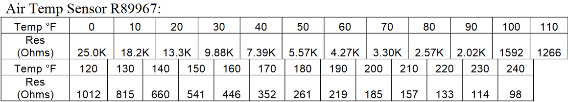
e.Using a digital multimeter set on resistance(ohms),measure the resistance between pins 4&5 (green and white wires),checking at the terminals of the orange connector.The resistance value should follow the chart below.If more than150ohms off these values,unplug the wiring at the sensor and re-check at the terminals of the sensor.If the value is still more than 150ohms off,the sensor is defective and should be replaced.
Standard Sensor R89966: